
Views: 0 Author: Site Editor Publish Time: 2026-11-08 Origin: Site


Chemical fires generate extreme thermal loads that melt standard protective gear within seconds. Sending human crews directly into the hazard zone is no longer a viable tactical option. You need heavy-duty robotics. However, simply attaching a remote-controlled chassis to a pressurized hose will not suppress an industrial inferno. Raw pump pressure must undergo a precise physical transformation into a highly targeted, weaponized stream of water.
In this comprehensive engineering guide, we break down the exact mechanical and fluid dynamics that make this hydraulic conversion possible. We focus heavily on how facility engineers optimize flow rates to ensure maximum cooling capacity during catastrophic events.
To properly evaluate industrial safety equipment, facility managers must first demystify the core physics of water delivery. The relationship between pressure and flow is frequently misunderstood. Confusing the two often leads to critical errors in equipment deployment on the fireground.
Pump pressure represents the pushing force generated by an industrial static water pump or a pressurized hydrant system. Measured in pounds per square inch or bar, pressure dictates how much force is available to move the fluid through your infrastructure. Nevertheless, high pressure does not automatically equate to a high volume of water successfully reaching the fire.
Flow rate is the actual volume of water delivered to the hazard zone over a specific period. This is the ultimate metric that extinguishes fires and cools steel structures. Measured in liters per second or gallons per minute, the flow rate determines the true thermal absorption capacity of your system.
Converting pressure into flow relies heavily on Bernoulli’s principle of fluid dynamics. As pressurized water travels through the system and reaches the robot's water cannon, it encounters a deliberate restriction at the nozzle. This restriction acts as a critical conversion point. It forces the high potential energy to transform instantly into high kinetic velocity. By mastering this physical conversion, engineers can accurately calculate and optimize the output, ensuring the machine delivers a stream powerful enough to punch through intense thermal updrafts without vaporizing mid-air.
Converting raw pump energy into a usable suppression stream requires a sequence of interconnected mechanical components. A water monitor fire fighting robot is not a standalone water source. Rather, it is a highly engineered delivery mechanism designed to manage and direct extreme hydraulic forces safely.
Water must first reach the chassis from a safe distance. Crews achieve this via large-diameter drag hoses connected to a primary drafting pump. Imagine dragging hundreds of feet of heavy, water-filled lines across a debris-littered refinery floor. These hoses must utilize durable, high-tensile synthetic materials to withstand severe abrasion while containing massive internal pressures. The intake manifold on the robot typically features specialized couplings that allow for rapid attachment. This seamless connection minimizes turbulence as the water transitions from the flexible hose into the rigid metallic body of the machine.
Once water breaches the intake, it travels through a network of internal plumbing. The engineering of this internal manifold dictates the machine's overall efficiency. Sharp right-angle bends create severe internal turbulence, which violently strips kinetic energy from the water and causes massive pressure drops. To circumvent this, industrial robotic units utilize swept bends and exceptionally smooth-bore internal linings. Aerodynamic internal routing ensures that the maximum amount of potential energy is preserved as the fluid directs upward toward the discharge cannon.
The monitor serves as the final exit point and remains the most complex component of the entire conversion process. It consists of heavy-duty swivels, precision servos, and the nozzle assembly itself. These servos allow the remote operator to aim the cannon with pinpoint accuracy, mechanically overcoming the immense physical resistance of pressurized water. Furthermore, the nozzle shapes the exiting water. It determines whether the energy is expended as a tightly focused solid stream for maximum reach, or a wide protective fog pattern designed for rapid heat absorption.
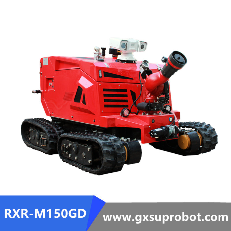
Understanding the journey of a water droplet from the initial pump to the final target provides absolute clarity on how robotic systems manage hydraulic forces. In practical terms, the entire process is a continuous uphill battle against energy loss.
Operations begin at the source. An external industrial pump engages, violently drawing water from a static reservoir and forcing it into the supply lines. At this initial stage, the water possesses its maximum potential energy. The pump must be meticulously calibrated. It needs to provide the pressure required to shape the stream at the very end, while maintaining a significant buffer of excess pressure to account for the physical resistance it will inevitably encounter along the way.
As the pressurized fluid travels through supply hoses, it aggressively rubs against the internal rubber lining. This physical friction, combined with the internal turbulence of water molecules colliding, converts a noticeable portion of the kinetic energy into ambient heat and sound. The longer the hose deployment and the faster the water moves, the more pressure is stripped away. Consequently, the external pump must continuously push harder to overcome this friction, guaranteeing that a sufficient baseline pressure survives the journey to reach the robot's intake manifold.
When the water finally reaches the monitor's nozzle, the physical diameter of the pipe suddenly narrows. Because water is an incompressible fluid, the exact same volume must pass through this smaller opening in the exact same amount of time. To accomplish this, the water is forced to accelerate rapidly. This sudden constriction acts as a hydraulic accelerator, converting the remaining static pressure into sheer forward velocity. The water violently exits the cannon as a high-velocity stream, effectively weaponizing the initial pump pressure.
Even equipped with a massive pump and a flawlessly engineered robot, external environmental and physical variables can severely degrade operational performance. Facility engineers must rigorously account for these factors when calculating expected output.
The physical dimensions of the supply line are undeniably the largest contributors to friction loss. Larger diameter hoses allow a far greater volume of water to move at a much slower velocity. This significantly reduces internal turbulence and friction. Conversely, attempting to force a massive volume of water through a narrow hose results in exponential pressure loss, ultimately rendering the robot entirely ineffective on the fireground.
| Hose Diameter | Fluid Velocity | Friction Loss Severity | Impact on Robotic Output |
|---|---|---|---|
| 2.5 Inches | Very High | Severe (High PSI drop per 100ft) | Highly restricted output; fails to cool industrial hazards. |
| 3.0 Inches | High | Moderate | Reduced physical reach and lower volume delivery. |
| 4.0 Inches | Moderate | Low | Optimal for standard municipal and light industrial operations. |
| 5.0 Inches | Low | Minimal | Maximum efficiency for 150 L/s heavy-duty robotic flow. |
Gravity plays a relentless role in fluid delivery. If crews deploy a robot up a steep concrete incline, or if it must angle its monitor sharply upward to spray over the rim of a towering petrochemical storage tank, the pump must actively fight gravity. This specific resistance is known as head pressure loss. Standard hydraulic calculations dictate that for every foot of vertical elevation, a specific amount of pressure is permanently lost. If a pump operator fails to calibrate the system to overcome this vertical resistance, the stream will inevitably fall short of the burning target.
The mechanical design of the nozzle dictates precisely how the final flow is utilized. Smooth bore nozzles feature a simple, tapered cylinder design. They provide maximum physical reach and a dense, solid stream that fiercely resists being broken apart by crosswinds or intense thermal updrafts. Fog nozzles feature complex internal baffles that shear the water into millions of smaller droplets. While fog nozzles are exceptional for absorbing ambient heat and creating protective thermal shields, they demand higher operational pressure to function correctly and generally offer significantly less physical reach.
Standard municipal flow rates are vastly inadequate for severe industrial hazards. In sectors such as petrochemical manufacturing, oil refining, and hazardous materials storage, the fire load is exceptionally dense.
The primary challenge in a petrochemical fire is the sheer thermal output. When a large-scale hydrocarbon fire erupts, the radiant heat generated is immense. If a standard volume of water is applied to a burning fuel tank, the extreme radiant heat will vaporize the water droplets mid-air long before they ever make physical contact with the fuel surface. The water turns to steam harmlessly, completely failing to cool the hazard.
To effectively combat these catastrophic industrial scenarios, facilities deploy a high flow firefighting robot. These specialized, heavy-duty machines handle extreme hydraulic throughput, often capable of delivering 150 liters per second, which translates to roughly 9,000 liters per minute. This massive volume ensures the water stream has the physical density and mass to punch directly through thermal updrafts.
Furthermore, this massive hydraulic output is absolutely critical for exposure protection and preventing a boiling liquid expanding vapor explosion. When a pressurized storage tank is exposed to an adjacent fire, the liquid inside boils and expands rapidly until the weakened steel tank catastrophically ruptures. Heavy-duty robots can lay down a continuous thermal blanket of cooling water over adjacent tanks, keeping the steel structure safely below critical failure temperatures.
Looking at recent developments in global industrial safety, there is a clear paradigm shift moving away from static water delivery toward dynamic, sensor-driven fluid management. Modern petrochemical facilities are increasingly integrating smart sensors with their overarching suppression networks.
Instead of relying solely on human estimation during the chaos of an emergency, incident commanders now utilize real-time algorithmic analysis. This technology perfectly matches industrial pump output with the robot's maximum nozzle capacity. This industry-wide transition toward automated hydraulic balancing significantly reduces the risk of catastrophic hose bursts while maximizing the cooling effect on critical infrastructure.
Modern industrial fire suppression is no longer just about brute mechanical force. Today's robotic suppression units integrate advanced telemetry and automated microprocessor systems to optimize fluid dynamics in real-time.
Operators controlling the unit from a safe distance rely heavily on onboard sensors to monitor performance. Digital flow meters and highly sensitive pressure transducers located within the intake manifold transmit real-time operational data back to the command console via secure radio frequencies. This continuous stream of telemetry allows the operator to see exactly how much pressure is reaching the machine. They can seamlessly communicate with the pump operator to throttle up or down as tactical conditions dictate.
Supply pressure in an industrial emergency is rarely perfectly stable. Hydrant pressures can fluctuate wildly as other units tap into the same water main. To counter this, advanced robots utilize automatic nozzles governed by onboard controllers. If the supply pressure drops unexpectedly, the system automatically constricts the nozzle's internal spring-loaded baffle. While this slightly reduces the total volume of water, it critically maintains the velocity and reach of the stream. Conversely, if pressure spikes dangerously, the baffle opens to relieve internal stress and prevent hose rupture.
According to Newton's third law, forcing thousands of liters of water forward at high velocity generates a massive backward reaction force. If a robot attempts to discharge 150 liters per second at a 90-degree lateral angle, the recoil could easily flip or derail the machine. To prevent this, smart robots are equipped with complex safety interlocks, including gyroscopes and load sensors. If the onboard software detects that the angle of the monitor threatens the physical stability of the chassis, it autonomously intervenes. It can apply heavy-duty track brakes, restrict rotation, or incrementally reduce the output to prevent a catastrophic rollover.
Investing in remote suppression technology requires a holistic, engineering-based approach to facility infrastructure. Purchasing a high-capacity machine is a wasted capital investment if your facility cannot actually support its operational hydraulic requirements.
The most common error in procurement is a glaring mismatch between the robot's maximum capacity and the facility's existing water infrastructure. You cannot force 9,000 liters per minute out of a robot if the facility's static fire pumps can only deliver 4,000. Before engaging in the procurement process, facility managers must conduct comprehensive flow tests on their hydrant systems to determine the true baseline capacity.
Buyers must rigorously evaluate the physical layout of their facility. Theoretical pump output measured at the pump house rarely matches the actual water delivery measured at the nozzle. If the most likely hazard zone is located 500 feet away from the nearest secure water source, the friction loss through 500 feet of hose will be substantial. The selected Fire Fighting Robot—such as a 4WD diesel unit—must be paired with hoses of appropriate diameter. The primary pumps must be rated to push water over that specific distance while still maintaining adequate residual pressure.
The required delivery rate is entirely dictated by the specific fire load of the environment. A standard logistics warehouse containing solid combustibles may only require a moderate flow rate to achieve full extinguishment. In stark contrast, a fuel depot requires maximum cooling capacity to prevent structural collapse. Buyers should calculate the thermal load of their specific hazard to determine the necessary cooling capacity in kilowatts, which directly translates to the required volume of water application.
Converting raw pump pressure into effective, targeted flow requires absolute precision. It seamlessly blends the immutable laws of fluid dynamics with cutting-edge advancements in robotic engineering. Ultimately, a high-pressure pump needs a highly capable machine to harness its energy, just as raw pressure is entirely useless without the right delivery system to shape it.
Facilities looking to upgrade their safety protocols must carefully evaluate their specific suppression needs. You must take into account friction loss, thermal loads, and existing water infrastructure. If you operate a high-risk petrochemical or industrial site, standard gear will fail when you need it most. Explore the advanced, heavy-duty robotic solutions available at GX SUPROBOT to find a chassis and monitor configuration that matches your exact hydraulic capabilities. Ensure that when disaster strikes, your system delivers the exact cooling power needed to protect critical assets and personnel.
The definition of a sufficient flow rate is entirely dependent on the specific application and the hazard profile of the facility. For standard municipal applications, a flow rate ranging from 1,000 to 3,000 liters per minute is typically adequate. However, heavy industrial sites, petrochemical plants, and aviation facilities demand vastly higher capacities. In these extreme environments, a high-capacity unit often requires 8,000 to over 9,000 liters per minute (approx. 150 L/s). This massive volume is necessary to overcome the immense thermal energy released by hydrocarbon fires and to provide adequate cooling to prevent secondary explosions.
No, higher pressure does not automatically equate to a higher flow rate. Pressure is the potential energy or the driving force pushing the water, while flow rate is the actual volume of water moved over a specific period. If the supply hose diameter is too narrow, or if the robot's nozzle is overly restricted, simply increasing the pump pressure at the source will not proportionally increase the volume of water delivered. Instead, the excess pressure merely increases the velocity of a much smaller stream, leading to excessive friction loss and severe internal turbulence.
To calculate the required pump pressure, engineers use a standard hydraulic formula: Engine Pressure = Nozzle Pressure + Friction Loss + Elevation Loss (or Gain) + Appliance Loss. You must know the optimal operating pressure of the robot's specific nozzle. Then, calculate the friction loss based on the diameter and length of the supply hoses. Finally, account for any uphill elevation the water must climb. Adding these variables together gives you the exact pressure the primary pump needs to output at the source.
Stream reach degradation is typically caused by a failure to overcome friction loss, resulting in inadequate nozzle pressure. If operators deploy too much hose, use a hose with too small a diameter, or encounter sharp kinks in the supply line, the kinetic energy of the water drops significantly. Additionally, selecting the wrong nozzle pattern (such as a wide fog instead of a smooth bore solid stream) or facing severe crosswinds will prematurely break apart the water stream, drastically reducing its effective physical reach.
Handling the immense reaction force generated by high-pressure water delivery requires a combination of mechanical engineering and smart software. Mechanically, these units feature a heavily weighted chassis, a very low center of gravity, and high-traction continuous tracks made of specialized industrial rubber or steel. Technologically, advanced models utilize onboard gyroscopes, tilt sensors, and accelerometers to continuously monitor balance. If the recoil pushes the machine dangerously close to its tipping point, the automated control system instantly intervenes by applying mechanical brakes, adjusting the cannon's trajectory, or incrementally reducing the water output.
Yes, the vast majority of industrial-grade platforms are dual-purpose, capable of delivering both plain water and firefighting foam. They utilize specialized, interchangeable monitor nozzles equipped with aeration tubes and internal baffles. When foam application is required, the high-pressure water stream is forced through a constriction in the nozzle, creating a vacuum known as the Venturi effect. This vacuum draws liquid foam concentrate into the water stream. The mechanical agitation within the nozzle then aggressively mixes the water, concentrate, and ambient air to produce a thick, expanded foam blanket essential for smothering liquid fuel fires.