Views: 0 Author: Site Editor Publish Time: 2026-05-29 Origin: Site


A structural frame alone cannot guarantee a successful autonomous deployment. The physical foundation of your mobile platform directly dictates sensor accuracy, environmental resilience, and operational scale. If your foundation lacks rigidity, the entire system becomes compromised.
Many engineering teams underspecify their hardware during initial design phases. This oversight quickly leads to mileage drift in SLAM algorithms, severe thermal throttling, and unmanageable maintenance overhead. You cannot simply fix fundamental hardware deficits using software patches. Heavy payloads and rough terrain will ruthlessly expose any design shortcuts.
We will break down exactly what features make a hardware platform reliable. You will discover an evidence-based evaluation framework to streamline your shortlisting process. By analyzing structural materials, drive mechanisms, and software openness, you will learn how to select a truly robust commercial Robot Chassis.
Structural capacity is dynamic: True payload capacity must factor in slope friction, dynamic stress, and material thermal conductivity (e.g., aluminum acting as a heat sink).
Drive mechanisms dictate software limits: Without precise closed-loop control and low-backlash transmissions, top-tier navigation algorithms will still suffer from cumulative odometry errors.
Safety requires hardware fail-safes: Heavy-duty applications demand mechanical self-locking systems (like worm gears) to prevent slope-sliding during power failures.
Ecosystem openness drives ROI: Hardware is a liability without open APIs, modular SDKs, and pre-allocated interfaces for LiDAR, cameras, and manipulators.
Vendor validation is critical: Commercial viability requires proven continuous aging tests (e.g., 48-hour stress tests) and accessible integration support.
Selecting the right materials and geometries sets the baseline for your robotic platform. You must evaluate these elements based on thermal properties, operational environments, and dynamic payload requirements.
Engineers often focus solely on the weight of structural materials. However, thermal conductivity and anisotropic stress responses matter just as much in high-performance environments.
Aluminum alloys, particularly the 6000 series, provide exceptional strength-to-weight ratios. More importantly, extruded aluminum acts as a massive integral heat sink. It draws heat away from high-power motor drivers and localized processing units. This passive cooling prevents thermal throttling during sustained operations.
Steel frameworks become necessary for ultra-heavy payloads. They offer unparalleled rigidity and impact resistance. However, steel introduces significant curb weight. You must compensate for this mass by upgrading the entire powertrain. Untreated steel also requires aggressive anti-corrosion surface treatments.
Avoid 3D-printed polymers like PLA or ABS for any commercial load-bearing components. Layered printing creates anisotropic stress weaknesses. These parts will unpredictably fracture under continuous dynamic loads.
Material | Primary Use Case | Thermal Management | Structural Weakness |
|---|---|---|---|
6000 Series Aluminum | Mid-to-heavy service robots | Excellent (acts as heat sink) | Lower ultimate tensile strength than steel |
Carbon Steel | Ultra-heavy industrial hauling | Poor (retains localized heat) | High curb weight demands massive motors |
3D Printed PLA/ABS | Rapid prototyping only | None (insulator) | Anisotropic stress points cause fractures |
You must assess the chassis shape against your exact deployment environment. Footprint geometry heavily dictates both internal capacity and external collision resilience.
Rectangular footprints maximize your internal component space. They allow for straightforward battery mounting, predictable wire routing, and high-density payload stacking. Most warehouse logistics robots rely on rectangular structures for these reasons.
Conversely, circular designs offer superior geometric defense. When equipped with outer roller arrays, circular platforms can physically deflect lateral impacts. The robot slides tangentially away from obstacles. This tangential sliding prevents catastrophic sensor damage in high-traffic commercial zones.
Best Practice: Always perform kinematic simulations on your chosen geometry to ensure it can maneuver through the narrowest chokepoints in your target facility.
Payload capacity is rarely a simple static number. Resting weight on flat ground does not translate to dynamic operational limits.
Verify that your chosen vendor provides clear documentation on CoG adjustments. Look for dedicated battery placement slots and configurable counterweight options. A low, centralized CoG prevents tip-overs during emergency braking scenarios.
Implementation risk often arises from miscalculated payloads. You must calculate the rated payload against the maximum operational incline and surface friction. A platform carrying 100kg on smooth concrete may fail to haul 50kg up a 15-degree carpeted ramp. Dynamic stress multiplies the effective load on the drive shafts.
Your robot can only perform as well as its drive mechanics allow. Navigation algorithms rely on predictable physical movements. Loose tolerances translate directly to software failure.
Different environments demand completely different locomotion strategies. You cannot force an indoor platform to perform off-road duties effectively.
Differential and Omnidirectional Drives: These configurations are ideal for flat, indoor warehousing. Mecanum or Swerve drives prioritize zero-radius turning, allowing robots to navigate incredibly tight aisles. However, omnidirectional wheels suffer from severe friction wear. They also exhibit poor cross-slope stability on uneven floors.
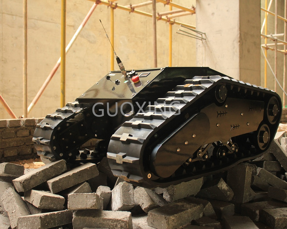
Tracked Systems: A high-performance Robot Tank Chassis is mandatory for outdoor, uneven, or high-friction environments. Tracks dramatically increase surface contact. They distribute weight evenly across mud, gravel, or steep inclines. However, tracked systems require robust differential operation. You need independent, high-precision encoder motors on each track to actively compensate for slip errors.
High-dynamic response relies on minimal mechanical slop. Traditional planetary gearboxes often introduce unacceptable levels of mechanical backlash. When the motor reverses direction, the slight gap between gear teeth creates a split-second delay. This delay wreaks havoc on precise odometry calculations.
For high-precision applications, evaluate platforms utilizing brushless motors paired with ball screws. Ball screws translate rotational motion into linear motion with near-zero backlash. Alternatively, use high-ratio industrial servos designed specifically to minimize deadband. These premium components ensure your software commands instantly translate into physical movement.
Trustworthiness in robotics heavily depends on fail-safe behaviors. Power outages or system crashes will inevitably occur in the field.
A core metric for heavy-duty chassis reliability is the presence of mechanical self-locking systems. Automatic electromagnetic brakes engage the moment power drops. Worm gear drives offer inherent self-locking properties due to their mechanical friction angle. These fail-safes guarantee the robot cannot dangerously freewheel down a slope during a power loss.
Common Mistake: Relying solely on software-based electronic braking. If the main controller loses power, software brakes fail entirely. Always demand physical, hardware-level locking mechanisms for loads exceeding 50kg.
Robots face continuous kinetic shocks and harsh environmental elements. A rigid, unprotected frame will quickly destroy both your hardware and your software map.
Autonomous navigation depends heavily on stable sensor data. Rigid chassis designs transmit ground vibrations directly up to the SLAM sensors. This vibration causes sensor jitter, which rapidly distorts the LiDAR point cloud.
A high-performance chassis must feature passive adaptive suspension. Tension spring-rocker mechanisms are highly effective. They maintain continuous ground contact without requiring active sensor input. This mechanical buffering absorbs jarring shocks.
By preventing optical misalignments, a robust suspension system directly reduces cumulative mapping errors. Your SLAM algorithm spends less compute power attempting to correct physical jitter.
Suspension Architecture | Vibration Transfer Rate | Typical Odometry Drift (per 100m) | Point Cloud Distortion Risk |
|---|---|---|---|
Rigid Frame (No Suspension) | High (>85%) | > 5.0% | Severe (High jitter) |
Basic Shock Absorbers | Medium (40-60%) | 2.0% - 3.5% | Moderate |
Tension Spring-Rocker System | Low (<15%) | < 0.5% | Minimal (Clean mapping) |
Environmental resilience requires rigorous protection against dust, water, and heat. Evaluate the IP ratings strictly against your operational realities. IP54 suffices for clean indoor logistics. However, outdoor platforms demand IP65 to IP67 ratings to survive heavy rain and fine particulate dust.
Ensure the chassis features heavy-duty rubber gaskets around all electronics enclosures. Look for powder-coated or anodized anti-corrosion surface treatments. Furthermore, the design must include dedicated active or passive thermal pathways. Sealed components will overheat quickly if the frame cannot adequately vent internal ambient temperatures.
Rolling resistance drains battery life rapidly. Look for platforms utilizing high-grade, sealed load-bearing bearings. These premium bearings drastically reduce rotational friction, extending deployment times.
For off-road configurations, inspect the track material. Specialized non-slip materials, such as reinforced nylon tracks with integrated Kevlar tension cords, prevent stretching over time. They maintain tight integration with the drive sprockets, eliminating skipped teeth during heavy acceleration.
Brilliant hardware remains a liability if you cannot communicate with it. Integration friction destroys development timelines and delays product launches.
Hardware is virtually useless without accessible software integration. Closed ecosystems force engineers to reverse-engineer basic motor controls. You must shortlist platforms offering unrestricted SDKs and open API architectures.
Look for native support for Robot Operating System (ROS and ROS2). The platform should expose underlying CAN bus and serial communication protocols. Seamless secondary development requires complete read/write access to motor states, encoder ticks, and battery telemetry.
Mounting external sensors should not require custom machining. The chassis must provide standardized mounting hole patterns. Extruded aluminum t-slots offer infinite adjustability for mounting brackets.
Furthermore, examine the internal wire management. High-performance models feature pre-routed, shielded wire channels. These physical barriers separate high-voltage motor cables from sensitive data lines. This segregation prevents electromagnetic interference (EMI) from corrupting your LiDAR and camera feeds.
Integrating third-party payloads requires adaptable power solutions. External manipulators, advanced edge computers, and varied sensors all demand different voltages.
Regulated Multi-Voltage Outputs: Ensure the onboard Battery Management System (BMS) offers clean 5V, 12V, and 24V rails.
Native Compatibility: These outputs natively power microcontrollers and upper-level manipulators without requiring clunky, custom step-down converters.
Overcurrent Protection: Each rail must feature independent fused protection. If a third-party camera shorts out, it should not trip the main motor power.
Deploying fleets into commercial environments requires strict hardware validation. You must evaluate the manufacturer's testing protocols and post-sale support infrastructure.
Do not accept prototypes marketed as production-ready units. Require definitive evidence of factory validation. A trustworthy vendor will openly provide data on their continuous aging tests.
Standard industrial validation demands 48 to 72 hours of uninterrupted load-bearing operation. The chassis must run under maximum rated payload at varied inclines to verify thermal stability. If a vendor cannot produce these stress test reports prior to shipment, their hardware poses a massive operational risk.
Hardware should accelerate your facility mapping, not hinder it. For chassis systems featuring integrated navigation stacks, strictly evaluate the time-to-map metric.
High-performance industrial platforms allow for rapid, reflector-free LiDAR SLAM deployment. You should be able to map a standard 10,000-square-foot facility and establish operational waypoints in less than a few hours. If the platform requires complex environmental retrofitting or manual grid measurements, it lacks modern deployment efficiency.
Engineering roadblocks will inevitably occur when marrying custom algorithms to new physical hardware. Assess the vendor's post-sale ecosystem thoroughly.
Access to 1-on-1 technical support forms a critical risk-mitigation factor. Engineering teams need direct channels to the manufacturer's engineers for kinematic algorithm integration. When retrofitting heavy top-modules, you need prompt, authoritative guidance on dynamic payload adjustments. A responsive vendor SLA ultimately protects your project deadlines.
The right hardware foundation perfectly aligns structural physics, precise motor control, and an open software architecture. When you thoroughly evaluate payload dynamics and insist on mechanical fail-safes, you protect your broader robotics investment.
Focus strictly on platforms that transparently document their payload limitations across various inclines. Utilize standard industrial materials like extruded aluminum to solve localized thermal issues naturally. Never compromise on suspension; passive adaptive mechanisms will directly preserve your SLAM integrity by isolating delicate sensors from kinetic shock.
Finally, prioritize vendors offering deep, unrestricted SDK access. Your engineering team needs open CAN bus protocols and multi-voltage power rails to seamlessly integrate top-modules. By demanding rigorous vendor validation and accessible APIs, you drastically derisk your product development timeline and ensure reliable field performance.
A: Rigid chassis transmit ground vibrations directly to SLAM sensors. High-performance suspension absorbs kinetic energy, preventing sensor jitter, which reduces point-cloud distortion and odometry drift. Without it, mapping algorithms struggle to reconcile physical bumps with sensor movement.
A: Opt for a robot tank chassis when operating in unstructured outdoor environments, deep mud, or steep inclines where maximum traction and passive obstacle-climbing capabilities are required. Tracks distribute weight efficiently over loose surfaces that would trap standard wheels.
A: Aluminum offers sufficient structural rigidity while functioning as a large, passive heat sink for electrical components. It is also highly modular (using standard extrusions) and significantly lighter. This reduced mass conserves battery life and improves dynamic acceleration.