
Views: 0 Author: Site Editor Publish Time: 2026-09-13 Origin: Site


Sourcing a rough terrain robot chassis for commercial deployment requires moving beyond basic prototypes. You must target enterprise-grade reliability to succeed. Applications like precision agriculture, pipeline inspection, and defense logistics demand absolute durability. Many off-the-shelf platforms fail under real-world stress. Inadequate suspension systems cannot absorb intense shock. Compromised load capacities warp structural frames. Poor motor integration leads to sudden power failures. You cannot afford unpredictable downtime during critical field operations.
This guide provides technical buyers and lead engineers a transparent evaluation framework. We outline how to assess mechanical platforms rigorously. You will learn to verify load dynamics, select track materials, and evaluate factory capabilities. Proper vendor selection guarantees long-term scalability. Our goal is to ensure your final platform meets stringent performance metrics.
Objective definitions separate successful deployments from costly field failures. We must define "rough terrain" clearly before comparing mechanical platforms. Light off-road use differs vastly from high-friction, variable-elevation environments. Your robots will encounter deep mud, construction rubble, and steep inclines. A robust platform handles variable elevations smoothly. Success requires matching the mechanical design to the specific terrain profile. Defining these parameters early prevents over-engineering or under-specifying the final build. Engineers must assess soil composition, moisture levels, and obstacle dimensions.
Mobility versus stability trade-offs dictate chassis geometry completely. A wider track base improves stability significantly. It prevents the robot from rolling on steep inclines. However, a wider stance increases the turning radius. It also demands a higher power draw during pivot turns. You must balance these factors based on your operational environment. Narrow tracks navigate tight inspection spaces easily. But they risk tipping over on uneven ground. Engineering teams must calculate the optimal track width early to ensure operational safety.
The payload reality often surprises new hardware buyers. Static load capacity means little in the field. Dynamic load capacity dictates true performance over uneven ground. Bumping over rocks multiplies the forces exerted on the frame. A chassis rated for 100 kilograms static might only handle 40 kilograms dynamically. Successful deployment requires defining your exact operational payload early. You must account for heavy sensors, robotic arms, and dense battery packs. Discuss these exact weight distributions before finalizing your order. Accurate payload mapping prevents catastrophic frame stress.
Precise engineering benchmarks eliminate dangerous field failures. You need realistic payload limits for safe operations. A full-metal platform chassis prevents mechanical torsion. It stops the frame from warping under maximum physical stress. Engineers use specific formulas to establish safe baselines. A common heuristic reduces the static capacity by fifty percent for dynamic operations. This simple calculation provides a crucial safety margin. It protects the chassis during sudden impacts. Requesting a structural breakdown helps verify these load thresholds.
Speed and gearing dictate traversal capabilities directly. Torque and speed share an inverse relationship in electric motors. High speed means lower available torque. High torque sacrifices top-end speed. You need substantial torque to climb obstacles safely. Guide your buyers to request detailed torque-curve data. Avoid relying on unladen top-speed claims. Unladen numbers look impressive on paper. They plummet quickly when you add a heavy sensor payload. Analyzing the gear reduction ratio provides a clearer picture of climbing power.
Power and endurance metrics require careful scrutiny during evaluation. Rough terrain drains batteries rapidly. Continuous slope climbing consumes massive amounts of power. High-friction turning generates heat and draws high electrical currents. You must request realistic amp-hour draw estimates. Partnering with a proven Tracked Robot Chassis Factory provides access to accurate benchmarking. They can supply data based on specific terrain profiles. This data prevents unexpected power loss in the field. It also helps you specify the correct battery chemistry.
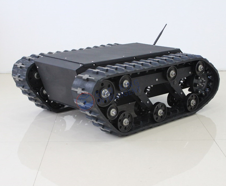
Track selection fundamentally alters field performance. Rubber tracks and metal tracks serve different operational needs. You must weigh their benefits against your specific environment. The wrong material accelerates wear and increases maintenance costs.
| Feature | Rubber Tracks | Metal / Composite Tracks |
|---|---|---|
| Vibration Control | Excellent. Absorbs minor ground shocks. | Poor. Transfers vibration to the chassis. |
| Terrain Grip | Optimal for smooth inclines and asphalt. | Optimal for deep mud, snow, and loose gravel. |
| Weight Factor | Lightweight, reducing overall power draw. | Heavy, demanding higher motor torque. |
| Durability | Vulnerable to sharp rocks and metal debris. | Highly resistant to cuts and abrasions. |
Rubber tracks offer several distinct advantages for specific applications. They produce much lower vibration during transit. They offer better grip on smooth inclines and urban surfaces. Rubber provides notable weight savings for the entire platform. However, high-debris environments expose their mechanical limitations. Sharp rocks and metal shards can tear rubber belts quickly. Some manufacturers use Kevlar reinforcement to extend the lifespan of rubber tracks. You should ask about internal reinforcement materials during your evaluation.
Metal and composite tracks excel in brutal conditions. Metal provides unmatched durability in deep mud and snow. These tracks dig into loose soil easily. This durability comes at a cost. Metal tracks require robust drive sprockets. They consume more energy due to their higher overall weight. Maintaining metal tracks also requires specialized lubrication and tensioning procedures.
Suspension and shock absorption protect your expensive payload. Independent suspension systems isolate the chassis from ground impacts. Christie or bogie suspension systems excel here. They are critical for sensor stabilization. LiDAR units and optical cameras distort without proper shock absorption. You should verify the shock-absorption tolerances strictly. Ask the manufacturer about damper adjustability. Adjustable dampers allow you to fine-tune the ride quality. This adjustment is vital when you change payload configurations frequently.
Not all manufacturers offer the same engineering expertise. You must differentiate true engineering partners from mere assemblers. Some facilities only assemble standard white-label parts. An OEM or ODM partner offers far more value. They perform finite element analysis (FEA) routinely. FEA identifies structural weak points before manufacturing begins. They handle custom chassis dimensioning perfectly. This ensures your specific components fit seamlessly into the core frame. A true engineering partner optimizes the entire structural design.
Compliance and IP ratings remain non-negotiable for field robots. Environmental protection guarantees operational longevity. Emphasize verifiable ingress protection for all electronics. IP65 or IP67 ratings represent the standard for professional applications. Motors and internal bays must remain completely sealed. Dust and water destroy unprotected electronics within hours. Verify these ratings through external testing reports. Never accept verbal assurances regarding environmental sealing.
Sourcing a Tracked Robot Chassis Factory,rough terrain robot chassis requires long-term supply chain planning. You need a reliable hardware partner. Avoid vendor lock-in on proprietary parts. This limits your future scalability.
Use the following checklist to evaluate factory scalability objectively:
System integration often introduces unexpected physical failures. Center of Gravity (CoG) shifts pose a major risk. Adding top-heavy payloads to lightweight bases causes rollovers. You must prevent this common deployment failure. Ask the factory for detailed 3D CAD files upfront. Simulate your payload distribution digitally before purchasing hardware. This simple software step saves thousands of dollars in ruined prototypes. Understanding lever arms and tipping moments ensures a stable platform.
Control system compatibility demands careful attention early in the process. Proprietary motor controllers create software bottlenecks. They complicate high-level robotic integration. We recommend factories offering open-source controller compatibility. Look for industry-standard communication protocols. CAN bus and RS232 or RS485 remain essential for industrial robots. Native ROS compatibility accelerates your software development cycle significantly. Open communication standards give your software team complete control over the drive system.
Thermal management prevents catastrophic hardware failures. Continuous high-torque operations generate immense internal heat. Stair climbing overworks motor drivers quickly. Thick mud traversal stresses drive motors continuously. Driver overheating causes sudden and dangerous shutdowns. The factory must mitigate this risk engineered into the frame. Look for robust chassis heat-sinking capabilities. Active cooling keeps internal components within safe thermal limits. A well-designed aluminum frame acts as a massive heat sink naturally.
Sourcing the right rough terrain robot chassis demands strict engineering procurement. It is never a simple catalog purchase. You are investing in a foundational platform for complex robotics. Careful evaluation prevents costly redesigns.
Follow these actionable next steps to ensure success:
Request structural test reports immediately. Ask for baseline CAD models today. Demand dynamic load specifications from your shortlisted tracked robot chassis factory. Begin the technical evaluation phase now to secure a highly reliable platform.
A: Standard lead times vary based on customization depth. Prototyping typically takes 4 to 8 weeks. This allows for structural adjustments and motor tuning. Bulk manufacturing runs usually require 8 to 12 weeks. Always confirm material availability and component sourcing timelines with your factory early.
A: Yes, a qualified manufacturer will adjust the suspension system. They can swap springs and dampers based on your payload distribution. Stiffer springs handle heavier static loads. Adjusted dampers control rebound over rough terrain. This ensures optimal sensor stabilization and prevents bottoming out.
A: Avoid relying solely on theoretical battery math. Request continuous-draw bench test data. Ask for real-world obstacle traversal video logs. Analyzing amp-hour draw during high-friction turns provides an accurate baseline. Practical testing always reveals thermal throttling and battery drain rates unseen in static calculations.
A: Field replacement depends on the track tensioning mechanism. Modern chassis designs use accessible tensioners for quick swaps. However, you must carry the correct tools. Always confirm the availability of spare links or belts directly from the factory to avoid extended operational downtime.