
Views: 0 Author: Site Editor Publish Time: 2026-09-19 Origin: Site


Developing robots for unstructured environments demands an unbreakable hardware foundation. The chassis serves as the critical failure point or primary success driver for applications in agriculture, infrastructure inspection, and border defense. You simply cannot compromise on this physical base. Unfortunately, off-the-shelf specifications frequently look impressive on paper but tell a different story outdoors. These generic platforms often fail completely in real-world mud, heavy rubble, or steep gradients without precise engineering alignment. Manufacturers quickly discover theoretical lab testing rarely matches harsh field conditions. It is time to transition your approach from simply browsing static spec sheets. You must actively evaluate a reliable Rubber Track Robot Chassis Supplier based on manufacturing capabilities, customization agility, and integration readiness. This guide reveals how to identify the perfect engineering partner for your next deployment.
Choosing the right manufacturing partner directly impacts your overall business viability. Track wear, motor burnout, and suspension failures cause massive operational headaches in the field. Field failures demand expensive retrieval logistics. They also cause severe reputation damage among your client base. Clients will not tolerate autonomous robots getting stuck in muddy agricultural fields. You need robust hardware built to endure harsh, unpredictable realities.
Time-to-market constraints pose another significant business risk. Relying on suppliers offering only rigid product lines limits your engineering agility. You might face months of delays waiting for minor design tweaks. Instead, seek out partners offering rapid iteration and CAD-level co-engineering. They help you adapt quickly to unexpected market feedback. A collaborative supplier essentially acts as an extension of your internal R&D team.
Establish clear success criteria before signing any supply contracts. A successful procurement strategy balances payload capability, power efficiency, and long-term parts availability. We recommend building an internal scoring matrix to weigh these factors objectively. Prioritize suppliers guaranteeing spare parts for at least five years. This commitment ensures your fleet remains operational long after the initial field deployment.
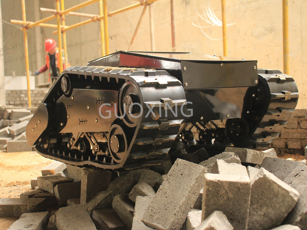
Assess how the prospective supplier calculates payload capacities. Do they measure static capacity on a flat warehouse floor? Or do they test dynamic loads on 30-degree inclines? You absolutely need dynamic testing data to ensure field reliability. A true all-terrain robot chassis must carry its maximum rated weight while actively climbing over heavy debris.
Evaluate track width and tread patterns carefully. Wider tracks minimize ground pressure in soft soils or deep snow. They prevent heavy robots from sinking. However, you must balance this width against hard-surface maneuverability. Extremely wide tracks struggle to turn smoothly on concrete surfaces. Optimal weight distribution across the entire footprint remains essential for balanced navigation.
| Terrain Type | Recommended Track Width | Tread Pattern Design | Primary Engineering Goal |
|---|---|---|---|
| Soft Soil / Mud | Wide (>150mm) | Deep, aggressive cleats | Maximize flotation, prevent sinking |
| Snow / Ice | Extra Wide (>200mm) | Staggered, sharp lugs | Increase grip, distribute weight |
| Urban Rubble | Medium (100mm-150mm) | Thick, reinforced rubber | Resist punctures, maintain agility |
| Concrete / Asphalt | Narrow (<100mm) | Shallow, smooth profile | Reduce turning friction, save battery |
Compare rigid frames against active or passive suspension systems. Rigid frames work fine for indoor, perfectly flat environments. However, rugged outdoors require advanced Christie or Bogie suspensions. These systems keep the rubber tracks planted firmly over uneven obstacles. Better ground contact equals better traction and safer ascents.
Verify the supplier’s track tensioning mechanisms thoroughly. Are they easily adjustable in the remote field? Operators must tighten tracks quickly to prevent dangerous derailments. Complex tensioners frustrate field technicians and delay missions. Keep it simple, durable, and easily accessible. A good design requires only standard hand tools for immediate tension adjustments.
Scrutinize the motor and gearbox selection closely. Look for high-torque, brushless DC (BLDC) motors. They offer superior power efficiency and much longer operational lifespans. Brushed motors wear out too quickly in demanding industrial applications. They require constant maintenance you cannot afford.
Check the Ingress Protection (IP) ratings on all drive components. You need at least IP65 or IP67 ratings for reliable water and dust resistance. Open motors will fail catastrophically in muddy agricultural environments. Your supplier must provide certified IP testing documentation to validate their marketing claims.
The "Standard" Trap:
COTS chassis certainly speed up your initial R&D phases. They get functional prototypes moving fast across the lab. However, they often trap you during final integration stages. Standard units typically require heavy modification to handle specialized payloads. You will struggle to mount custom robotic arms or heavy LiDAR setups. The generic frame simply lacks appropriate mounting points. Drilling into a standard frame often voids warranties and weakens structural integrity.
Supplier Customization Capabilities:
Evaluate the supplier's willingness to modify basic dimensions. Will they alter track materials for your specific use case? Kevlar-reinforced rubber significantly boosts durability against sharp rocks and metal debris. Can they upgrade gear ratios to deliver higher torque? A flexible partner adapts the base model to your exact physical needs. They never force you into a pre-built box.
Scalability Risk:
Ensure the supplier handles volume scaling effectively. Many small shops can build a fantastic one-off custom prototype. However, can they transition to consistent, batch-manufactured production runs? Quality degradation frequently occurs during this crucial jump. Audit their assembly lines. Look for standardized quality control processes governing every batch.
| Evaluation Metric | COTS Chassis | Custom Partner Solutions |
|---|---|---|
| Prototyping Speed | Very Fast (Days) | Moderate (Weeks) |
| Payload Integration | Difficult, requires adapters | Seamless, pre-drilled to spec |
| Component Upgrades | Limited to factory options | Highly flexible (motors, tracks) |
| Long-Term Scalability | High risk of forced obsolescence | Controlled, predictable supply |
Examine the hardware frame for standard mounting profiles. Pre-drilled payload decks save your engineering team hours of fabrication time. You should easily bolt down sensors, batteries, and compute units without custom machining. This modularity accelerates your entire development timeline.
Check the payload center-of-gravity (CoG) flexibility. Your specific sensory equipment might be quite top-heavy. The chassis must allow low-mounting battery trays to offset this top weight. Proper CoG management prevents dangerous rollovers on steep gradients. It keeps your expensive sensors safe.
Here are essential mechanical modularity checks you must perform:
Demand complete transparency regarding motor controller specifications. You absolutely need clear, comprehensive datasheets. Evaluate compatibility with open-source frameworks like ROS or ROS2. This deep compatibility saves massive software engineering time. Your team can focus on autonomy algorithms rather than low-level motor driving.
Standard communication protocols remain non-negotiable. Look for native CAN bus, RS232, or PWM support. They reduce your software engineering overhead significantly. CAN bus provides excellent telemetry feedback for advanced diagnostics. Your programming team can plug and play rather than write custom driver wrappers from scratch.
Supply Chain Transparency:
Probe where the supplier sources their internal components. Ask about raw rubber origins, motor manufacturers, and controller brands. This supply chain transparency mitigates geopolitical or logistical bottlenecks. You avoid sudden production halts when global shipping slows down. Reliable suppliers happily share their component sourcing strategies.
Testing and Validation Data:
Request empirical testing data constantly. Ask for continuous runtime limits and obstacle clearance thresholds. Request mean time between failures (MTBF) statistics. Reject suppliers relying solely on theoretical CAD simulations. You need hard proof from actual dirt, gravel, and mud.
Follow this specific sequence when auditing a supplier's test data:
Prototyping & MOQ Policies:
Look for partners offering highly accessible prototyping phases. They should provide clear, affordable pathways to low-volume production runs. Avoid suppliers demanding immediate, high minimum order quantities (MOQs). High MOQs tie up your startup capital way too early in the development cycle. A supportive supplier grows alongside your production needs organically.
Sourcing an all-terrain robot chassis requires forming a strategic engineering partnership. It is never a simple commodity purchase. Your field success depends entirely on hardware durability and software integration readiness. Take the necessary time to vet suppliers well beyond their glossy marketing brochures.
A: A realistic lead time ranges from 4 to 8 weeks for an initial prototype. This window heavily emphasizes the necessary engineering review time. The supplier must translate your payload and terrain requirements into modified CAD designs before manufacturing begins.
A: Preventing derailment requires a superior guide wheel design and robust tensioner adjustability. Ensure your supplier uses deep-grooved guide wheels. Additionally, the tensioning mechanism must allow quick, secure field adjustments using standard hand tools to keep tracks properly tensioned over debris.
A: Yes, retrofitting is possible but often challenging. Successful autonomous retrofitting requires high-resolution wheel encoders and compatible motor drivers. You must ensure the existing controllers support ROS integration via CAN bus or serial communication for precise movement commands.
A: You must provide a comprehensive spec sheet. Include your target payload weight, specific terrain type, maximum incline angle, desired top speed, and required control protocols. This information allows the supplier to select the correct motors and suspension architecture.