


Why do standard wheeled vehicles constantly get stuck in deep mud, soft sand, and rugged debris? Continuous track systems solve this mobility challenge by spreading machine weight over a massive ground contact area. Building your own custom continuous tracks requires careful engineering, precise component alignment, and durable material choices. In this complete guide, you will learn how to design, fabricate, assemble, and optimize high-performance track systems for demanding robotic applications.
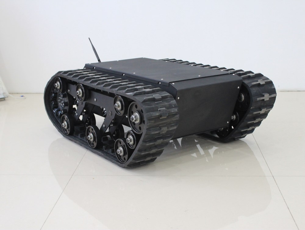
● Fabricating reliable tank treads requires precise matching between track link pitch and drive sprocket tooth profiles.
● Material selection balances durability and weight, ranging from heavy-duty reinforced rubber to lightweight engineering polymers or robust aluminum links.
● Proper track tensioning mechanisms prevent track derailment, reduce drive system strain, and extend component operational lifespan across rough terrain.
● Integrating independent suspension systems improves ground traction, protects sensitive internal payloads, and absorbs heavy shock loads.
● Pre-engineered tracked robot chassis offer a faster, field-tested alternative to custom DIY builds for demanding commercial and industrial missions.
Continuous track assemblies rely on a balanced network of mechanical parts working in harmony. Before cutting metal or printing prototype components, you must understand how each internal element supports vehicle weight and transmits mechanical force.
A complete continuous track system consists of several crucial mechanical parts:
● Track Links (Segments): The outer modular plates that make contact with the ground and provide surface grip.
● Connecting Pins: Precision rods that hinge individual segments together into a flexible continuous loop.
● Drive Sprockets: Toothed wheels connected directly to the drive motor that mesh with the track loop to push the vehicle forward.
● Idler Wheels: Unpowered wheels located at the opposite end of the drive sprocket that maintain track alignment and tension.
● Track Rollers (Bogie Wheels): Lower wheels that distribute vehicle weight evenly along the bottom portion of the track.
Note: Aligning drive sprockets and idler wheels along the exact same center axis is essential to stop the track loop from walking off the guide rollers during sharp skid-steer turns.
The distance between the center points of two adjacent pin holes is called the track pitch. Drive sprocket teeth must match this exact spacing. If the sprocket pitch is off by even a fraction of a millimeter, track links will bind, jump teeth, or wear down rapidly under heavy motor load.
Tracks outperform traditional tires because they dramatically increase the vehicle contact patch. To calculate nominal ground pressure, divide the total operational weight by the total surface area of both tracks resting on the floor. Lower ground pressure prevents heavy machines from sinking into soft mud, deep gravel, or snow.
Building functional continuous tracks requires an organized step-by-step approach from raw calculations to final track tensioning on your vehicle chassis.
Begin by determining the overall chassis footprint and required ground clearance. Calculate the total pitch length by measuring the distance between drive wheel centers, adding the pitch circumferences of the drive sprocket and rear idler, and dividing that total by your chosen link pitch value.
Choose a manufacturing process based on your target payload weight, working environment, and workshop tools:
● 3D Printing (FDM/SLA): Ideal for lightweight prototypes using durable materials like Nylon, TPU, or Polycarbonate.
● CNC Machining: Excellent for high-strength aluminum or steel links designed for heavy-duty industrial tasks.
● Urethane Casting: Great for producing flexible rubberized track segments with custom tread patterns.
Tip: For medium-duty robotic prototypes, 3D printing individual track modules with reinforced Nylon carbon fiber filament offers an excellent balance of low rotational mass and high impact strength.
Fabricate individual track segments while maintaining tight pin-hole tolerances. Incorporate external tread lugs on the bottom face for cross-country grip, and design internal guide teeth on the top face to ride securely between your roller wheels.
Join the track segments using hardened steel pins, shoulder bolts, or stainless steel rods. Secure the pins at both ends using circlips, threaded locknuts, or press-fit brass bushings so lateral forces cannot push the joint pins out during heavy operation.
Machining or printing matching drive sprockets requires matching the tooth pocket shape to the outer profile of your track pin joints. Install sealed deep-groove ball bearings inside idler wheels to allow smooth, low-friction rotation under heavy track tension.
Wrap the completed track loop around the drive sprocket, lower guide rollers, and rear idler wheel. Connect the final master link pin, then adjust your tensioner until the top span of the track shows a minimal, controlled amount of physical slack.
Selecting the correct material determines how well your continuous tracks hold up against abrasive dirt, sharp rocks, and high mechanical friction.
Continuous rubber tracks reinforced with internal steel cords offer smooth, quiet operation across asphalt and concrete. They deliver exceptional high-speed vibration dampening and protect delicate internal electronic sensors from harsh shock impacts.
All-metal segmented tracks excel in extreme environments involving high thermal stress, sharp rubble, or corrosive chemicals. Stainless steel pins combined with heavy aluminum links support massive vehicle payloads without suffering structural fatigue.
High-density polyethylene (UHMW-PE), acetal (Delrin), and glass-filled nylon provide lightweight alternatives to metal tracks. These engineering polymers offer exceptional wear resistance, self-lubricating qualities, and low surface friction while keeping motor power consumption low.
Improper tension is the leading cause of thrown tracks and broken motor gearboxes. Building a dynamic tensioning system ensures reliable operation under heavy side loads.
Spring-loaded linear tensioners automatically compress when small rocks or debris pass between the track link and sprocket teeth, preventing track snapping. Hydraulic tension adjusters or grease-cylinder systems offer precise, high-force tensioning for heavy-duty commercial track frames.
To stop tank treads from slipping off their guide wheels during aggressive skid-steering maneuvers:
● Incorporate continuous internal center guides on every track link module.
● Use deep double-flanged track rollers that sandwich internal link guide teeth.
● Keep chassis alignment rigid to prevent torsional frame twisting under load.
Continuous track drives demand significantly higher rotational torque than wheeled systems due to ground scrubbing during turns. Pair high-efficiency brushless motors with planetary gearboxes or high-ratio worm drives to ensure smooth, controlled skid steering.
Adding suspension transforms a rigid, bumpy ride into an agile platform capable of maintaining maximum traction across uneven terrain.
Independent suspension systems allow individual track rollers to lift independently over obstacles while keeping the outer track loop flat against the ground surface.
Christie suspension designs feature long-articulation swing arms connected to internal coil springs. This configuration delivers long vertical wheel travel, absorbing hard ground impacts and keeping payload sensors stable during high-speed cross-country runs.
● Rigid Frameworks: Simple to construct, lightweight, and low cost, but transfer all terrain vibration directly into the chassis body.
● Flexible Suspension Layouts: Complex to build, but deliver vastly superior ground traction, higher speed capability, and reduced wear on track link pin joints.
Note: Integrating flexible rubber dampeners between the track frame and main body structure significantly reduces high-frequency mechanical vibrations without adding complex moving suspension links.
Thorough field testing helps identify mechanical weaknesses before deploying your custom platform into real-world work sites.
Test your assembled track loop across varied surfaces, including loose sand, wet mud, steep inclines, and sharp obstacles. Measure motor drive current draw during hard 360-degree skid turns to confirm your motor gear reduction handles peak mechanical resistance.
Inspect the inner track face and sprocket teeth after initial test runs:
● Uneven Sprocket Wear: Indicates pitch mismatch or bent drive shafts.
● Polished Inner Guide Teeth: Signals wheel misalignment or excessive chassis flex.
● Stiff Joint Pin Rotation: Points to dirty pin joints, tight pin hole tolerances, or poor lubrication.
Keep track assemblies performing reliably by clearing dirt from sprocket tooth pockets after every field operation. Inspect joint pins regularly for bending, verify track tension slack, and replace worn rubber or metal links promptly.
Building custom continuous tracks from scratch provides ultimate freedom, but engineering custom components demands significant development time, testing equipment, and machining expertise.
Consideration Factor | Custom DIY Build Strategy | Pre-Engineered Tracked Chassis |
Development Time | High (weeks to months of design & machining) | Minimal (ready for immediate payload integration) |
Manufacturing Cost | Low upfront materials, high tooling costs | Single, predictable hardware investment |
System Reliability | Requires iterative testing and bug fixes | Factory tested for high load and harsh weather |
Custom Flexibility | Unlimited link geometries and dimensions | Standardized mounting plates and expansion ports |
Pre-engineered tracked platforms solve tough mechanical engineering challenges right out of the box. Factory-built options feature fully sealed drive systems, high-torque brushless drive assemblies, durable rubber track loops, and robust suspension setups designed for extreme industrial conditions.
Selecting a pre-built tracked chassis does not mean sacrificing customization. Industrial platforms provide open mounting interfaces, allowing engineering teams to mount custom control hardware, robotic arms, thermal cameras, or specialized sensors onto a rock-solid drive base.
Building durable tank treads requires careful attention to pitch engagement, material selection, dynamic tensioning, and suspension design. Integrating these mechanical fundamentals ensures superior off-road traction and high operational reliability across rough environments. For teams seeking field-tested durability without the lengthy prototype phase, Guoxing delivers high-performance tracked chassis solutions designed to excel in demanding industrial missions.
A: High-strength rubber, reinforced nylon, and lightweight aluminum alloys offer the best balance of wear resistance, traction, and structural strength for custom tank treads.
A: Calculate pitch by measuring the exact center-to-center distance between consecutive link pins, ensuring your drive sprocket tooth profile matches that dimension to prevent binding.
A: Derailment on custom tank treads usually stems from loose track tension, misaligned sprocket wheels, flex in the chassis, or insufficient center-guide height on the track links.
A: Pre-built chassis save months of testing by offering factory-tuned suspensions, sealed motors, and proven continuous tank treads designed for immediate heavy-duty deployment.