
Views: 0 Author: Site Editor Publish Time: 2026-09-24 Origin: Site


The chassis serves as the physical foundation of your robotic system. You must choose it carefully. Selecting the wrong base often triggers cascading failures. These failures negatively affect payload capacity, power management, and navigation reliability across the board. Moving a robotics project from an initial prototype to a full commercial deployment requires a massive shift in focus. You must look far beyond basic mobility metrics. Engineers need to prioritize rugged durability, hardware integration readiness, and specific environmental constraints. This article gives you a rigorous, practical framework to evaluate these crucial factors. We will help you align your hardware choices directly to your complex technical requirements. You will learn how to balance harsh operational environments against tight commercial timelines. By the end of this guide, you will understand exactly how to properly Select Robot Chassis models that guarantee long-term operational success.
You must evaluate where the robot operates before looking at hardware specifications. The operating environment dictates every subsequent design choice. Ignoring environmental factors guarantees rapid hardware failure.
We categorize operational environments into two primary domains:
Next, you must assess your payload dynamics. Vendors often advertise impressive static payload capacities. However, static figures only tell half the story. A static payload defines what the base holds while stationary. Dynamic payload defines what it transports safely in motion. You must consider acceleration forces and braking momentum. High momentum can easily tip a poorly balanced unit during emergency stops.
Center of Gravity (CoG) plays a massive role in dynamic stability. High mounting points shift weight distribution upward. This vertical shift demands higher motor torque to maintain stability during turns. It also increases the risk of rollover on uneven terrain. You should always mount heavy components like batteries and primary motors as low as possible.
Finally, power and autonomy demands require careful calculation. A beautiful design fails if the battery dies midway through a task. Follow these steps to size your electrical requirements accurately:
Selecting the right kinematics ensures your robot navigates its environment efficiently. Let us break down the primary locomotion types available on the market.
Wheeled chassis platforms represent the most common choice. They offer excellent efficiency on appropriate surfaces. We can divide wheeled systems into three main categories. Differential drive systems offer high maneuverability. They use incredibly simple control logic. Two independently driven wheels steer the robot by spinning at different speeds. These bases work best for flat, indoor environments. Omnidirectional or Mecanum wheels excel in tight, constrained spaces. They perform complex lateral maneuvers easily. However, they suffer from severe vibration issues. They also lack sufficient traction on uneven outdoor ground. Ackermann steering mimics standard automotive designs. It proves highly energy-efficient for outdoor usage. It handles high-speed, long-distance traversal extremely well. It does lack zero-degree pivot turning capabilities.
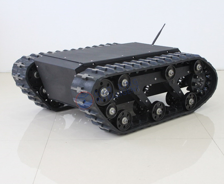
Tracked chassis platforms use continuous rubber or steel tracks instead of wheels. They provide superior weight distribution over soft ground. They handle obstacle clearance and slope-climbing exceptionally well. They remain strictly essential for heavy-duty off-road applications. Tracked platforms do carry notable downsides. They have much lower top speeds. They consume significantly more power due to track friction. They also risk tearing up soft surfaces during sharp pivot turns.
Suspension realities often make or break an advanced application. You must protect sensitive upper-tier sensors from severe vibration damage. Devices like expensive LiDAR units fail quickly under constant mechanical shock. Address this by integrating specialized suspension setups. Rocker-bogie mechanisms allow wheels to climb over tall obstacles while keeping the main body stable. Independent shock-absorbing suspensions isolate the main frame from harsh impacts entirely.
| Locomotion Type | Ideal Environment | Primary Advantage | Key Limitation |
|---|---|---|---|
| Differential Wheeled | Indoor, Flat Surfaces | Simple control logic, highly agile | Struggles heavily on rough terrain |
| Mecanum Wheeled | Indoor, Tight Spaces | Omnidirectional lateral movement | Poor outdoor traction, high vibration |
| Ackermann Steered | Outdoor, Long Distance | High speed, excellent efficiency | Cannot perform zero-degree turns |
| Continuous Tracked | Outdoor, Uneven Terrain | Superior slope and obstacle clearance | High power consumption, lower speed |
Choosing the right construction materials ensures your robot survives its daily tasks. We rely on a straightforward material selection matrix to guide these crucial engineering decisions.
Aluminum alloy stands as the absolute industry standard. It balances overall weight and structural rigidity perfectly. It fits most commercial applications seamlessly. Manufacturers easily machine aluminum into complex modular shapes. Carbon fiber comes at a steep premium cost. It offers ultra-lightweight performance and high stiffness. Engineers reserve it for high-speed drones or highly specialized agility tasks. Steel becomes completely necessary for ultra-heavy-duty payloads. It provides unmatched tensile strength. However, steel introduces massive weight penalties. This extra physical mass demands continuous higher current from the motors. It drains battery life rapidly.
Ingress Protection (IP) ratings dictate environmental durability. You cannot deploy indoor robots outside without checking these ratings. IP54 serves as the absolute minimum baseline for general commercial use. It handles light ambient dust and occasional water splashes. Industrial sweepers usually feature this rating. Agricultural or tactical applications demand much more robust protection. They require IP65 or IP67 ratings. These higher ratings withstand heavy dust storms, thick mud, and direct pressure washdowns.
You must actively scrutinize the physical sealing of critical components. Water and dust destroy open motor housings quickly. Gearboxes and electrical enclosures need incredibly tight seals. Always verify these protections before field deployment. A minor water seal failure often ruins thousands of dollars of internal electronics instantly. Check cable entry glands specifically, as they represent the most common failure points.
A strong physical frame means nothing without solid digital integration. Your chosen base must communicate smoothly with higher-level computing systems. Do not overlook the electrical and software ecosystem.
Start by reviewing the available control and communication interfaces. Ensure the hardware supports proven industry-standard protocols. CAN bus, RS232, RS485, and Ethernet represent the necessary baseline. CAN bus offers incredible noise immunity in factory settings. Ethernet provides massive bandwidth for sending high-resolution encoder data. You also need open-source framework compatibility. Look for reliable ROS or ROS2 driver availability. A vendor supplying native ROS2 nodes saves your team weeks of software engineering effort. Clear API documentation prevents major integration bottlenecks down the line.
Next, evaluate sensor and power integration features carefully. Mounting flexibility remains highly important for rapid prototyping. Look for standardized aluminum extrusion slots along the frame. Pre-drilled threaded hole matrices also help immensely. They allow you to add LiDAR, depth cameras, and modular robotic arms easily. Without these, you will waste days fabricating custom mounting brackets.
Power distribution boards (PDB) keep your external systems running safely. A robust PDB offers multiple regulated voltage outputs. You will likely need 5V, 12V, and 24V channels simultaneously. These channels power external compute units directly. They keep modules like the NVIDIA Jetson running smoothly. They also feed your navigation sensors safely from the main traction battery. A dedicated PDB isolates sensitive logic boards from harsh motor voltage spikes. This prevents random computer reboots during heavy acceleration.
Choosing a vendor requires exactly as much scrutiny as choosing the physical hardware. A comprehensive robot chassis selection guide must deeply address the buy versus build dilemma.
Evaluate the engineering hours required to build a custom unit from scratch. Compare this effort against integrating a proven commercial-off-the-shelf (COTS) platform. COTS solutions usually win for rapid commercial deployments. They save your team massive amounts of internal development time. They let your robotics engineers focus purely on autonomy software rather than debugging basic mobility mechanics. Building custom drive trains often traps teams in endless hardware iterations.
Apply strict vendor evaluation criteria during your initial shortlisting phase. Documentation quality reveals a lot about a company. A severe lack of wiring schematics or accurate 3D CAD models serves as a massive red flag. You cannot design custom payloads without accurate step files. Unresponsive technical support guarantees future deployment delays. You need a responsive engineering partner, not just a distant parts supplier.
Scalability and production lead times dictate your long-term commercial success. Ask hard questions about their manufacturing capabilities. Can the vendor scale up production quickly? They might provide one evaluation unit easily for initial prototyping. Can they deliver fifty identical units for your fleet deployment? Investigate their component supply chain resilience. A broken vendor supply chain halts your entire commercial rollout immediately. Ensure they stock critical replacement parts like motor drivers, encoder cables, and track belts locally.
Selecting the right base dictates the technical success of your entire robotics project. You must establish a strict, objective path for evaluation. Start by defining the physical operating environment clearly. Match the locomotion type directly to those specific terrain demands. Evaluate weight distribution and dynamic payload limits aggressively. Verify your hardware electrical interfaces and software integration readiness early in the design cycle. Finally, vet your chosen vendor for production scalability and responsive technical support.
We highly recommend investing in thoroughly documented commercial systems. A slightly more expensive platform offering native ROS2 support pays off extremely quickly. It saves thousands of dollars in internal software engineering and hardware debugging time down the line. It accelerates your product time to market significantly. It also prevents catastrophic failures in the field.
Take action today to push your project forward. Review specific mobility platforms relevant to your exact industry. Download detailed engineering specification sheets for side-by-side component comparisons. Contact a dedicated engineering team for a comprehensive payload consultation. Make your foundational hardware decisions with absolute confidence.
A: Agricultural tasks require navigating unpredictable, muddy, and highly uneven terrain. Tracked platforms or large-wheeled differential drives offer the best performance here. They provide superior weight distribution and excellent obstacle clearance. You must prioritize independent suspension systems to stabilize heavy farm payloads. Always ensure the unit carries an IP65 or higher environmental rating to withstand severe water, mud, and dust exposure.
A: Calculating motor torque requires a specific physics formula. You multiply the total mass of the robot by the driving wheel radius. Factor in the maximum expected incline angle you plan to climb. Include the desired acceleration rate to overcome initial static friction. Engineers strongly advise adding a 20 to 30 percent safety margin to this final calculation. This prevents motor stall conditions under unexpected dynamic loads.
A: Generally, you should avoid using Mecanum wheels outdoors. These wheels feature small, unprotected diagonal rollers. Dirt, gravel, and biological debris quickly jam these precise mechanisms. Mecanum systems also suffer from exceptionally poor traction on loose or uneven surfaces like wet dirt. Furthermore, their rigid mechanical mounting structures usually lack the suspension needed to protect sensitive payloads from constant outdoor vibrations.
A: A chassis serves solely as the bare hardware foundation. It includes the structural frame, traction motors, wheels, internal battery, and basic motor drivers. It cannot perform any tasks independently. A complete Autonomous Mobile Robot (AMR) builds entirely upon this base. Users or systems integrators must add high-level computing modules, advanced navigation LiDAR sensors, and dedicated autonomy software to make it intelligent.