
Views: 0 Author: Site Editor Publish Time: 2026-07-24 Origin: Site


Moving extreme payload weights across unstable, unpredictable terrain presents a monumental engineering challenge. Without the right mobility system, heavy vehicles will inevitably sink or completely lose traction in harsh environments. Engineers must overcome deep mud, loose sand, and jagged rocks to keep operations running smoothly. DIY-friendly tank mechanics initially solved this problem out of pure necessity on the battlefield. Today, commercial and industrial sectors adapt these exact same principles. They use them for heavy duty construction machinery, robotics, and advanced agriculture equipment.
Understanding the fundamental physics of continuous track systems remains an absolute prerequisite before evaluating or designing a mobility solution. A reliable undercarriage dictates the success of any high-stakes project. You will discover the precise mechanics behind how these continuous systems operate under load. We will also explore the critical engineering specifications needed to ensure optimal performance in demanding conditions.
Continuous Track Mechanics: Tank treads function by perpetually laying down their own flat road, drastically increasing surface area and minimizing ground pressure.
Component Synergy: A viable tracks chassis relies on the precise alignment of drive sprockets (power), idler wheels (tension), and road wheels (weight distribution).
Operational Trade-offs: While treads offer unmatched traction and load-bearing capabilities on soft terrain, they incur higher friction, lower top speeds, and intensive maintenance costs compared to wheeled systems.
Procurement Logic: Choosing between steel and continuous rubber tank treads depends entirely on the operational environment, payload weight, and required turning radius.
Engineers often refer to continuous tracks as an endless road system. Wheeled vehicles push through mud or snow. They sink until they find a solid bottom layer. Continuous tracks operate using a completely different physical principle. The vehicle moves forward by continuously laying a static track flat onto the ground. The road wheels roll over this flat surface. The rear assembly then picks the track back up. It feeds it forward over the top of the vehicle. This creates a perpetual cycle of movement. The track itself never actually slides against the ground. It remains completely stationary while the vehicle rolls across it.
A functional mobility system relies on several interdependent mechanical parts. Each component plays a specific role in keeping the vehicle moving. You must understand how these elements interact to design a reliable chassis.
Drive Sprocket: This toothed wheel transfers power directly from the transmission. It sits at either the extreme front or rear of the vehicle. The teeth physically engage the track links. It pulls the entire track system forward or backward.
Idler Wheel: You will find the unpowered idler wheel at the opposite end of the chassis. It serves two primary functions. It manages the overall track tension. It also absorbs massive frontal impacts when the vehicle strikes obstacles.
Road Wheels (Bogies): These unpowered wheels line the bottom of the assembly. They press the track firmly into the ground. They distribute the massive dead weight of the vehicle evenly across the flat track surface.
Track Links and Pins: These modular segments form the endless loop itself. Steel plates interlock using hardened metal pins. Reinforced rubber bands use embedded steel cables for similar strength. They bear the brunt of all ground friction.
These components must maintain perfect geometric alignment. If the idler wheel shifts slightly out of parallel, the entire track will derail. Proper engineering ensures these forces remain balanced. The drive sprocket pulls the track tight across the top. The road wheels push it down. The idler wheel keeps it aligned.
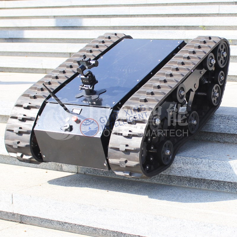
The core advantage of any continuous track system lies in ground pressure reduction. Ground pressure measures how much force a vehicle exerts on a specific area of terrain. Engineers calculate this in Pounds per Square Inch (PSI). A massive surface area allows heavy vehicles to float over soft ground. Without this physical property, tanks and heavy excavators would sink immediately into mud.
Let us look at a standard engineering baseline. A main battle tank weighs roughly 60 tons. It exerts surprisingly little pressure on the earth beneath it.
Entity or Vehicle Type | Approximate Operational Weight | Average Ground Pressure (PSI) |
|---|---|---|
Standard Wheeled Tractor | 15,000 lbs | 40 - 50 PSI |
Average Human Adult (Standing) | 180 lbs | 16 - 20 PSI |
Heavy Main Battle Tank | 120,000 lbs | 14 - 15 PSI |
Light Tracked Robot | 500 lbs | 2 - 4 PSI |
The numbers reveal a striking reality. A 60-ton tracked vehicle exerts less ground pressure than a human foot. The massive surface area of the track distributes the force incredibly well. This engineering principle transforms how vehicles interact with challenging landscapes.
Traction relies heavily on physical grip rather than just surface friction. Engineers design track pads using raised profiles called cleats or grousers. These metal or rubber ridges bite aggressively into soft soil, snow, or mud. They create a shear plane within the earth itself. The engine pushes against this solid wall of compacted dirt. This prevents the vehicle from slipping sideways. It maximizes forward thrust in environments where smooth tires would just spin endlessly.
This physics principle translates directly into operational uptime for heavy machinery. You avoid massive delays caused by sunken vehicles. A properly configured chassis prevents severe terrain damage. Agriculture equipment relies on this to avoid compacting delicate farm soil. Construction crews use tracked machines to keep projects moving during heavy rain seasons. Eliminating vehicle recovery efforts keeps industrial operations running safely and efficiently.
Choosing a mobility system forces engineers to accept specific performance compromises. You must contrast continuous tracks against wheeled configurations across several critical operational metrics. No single solution works perfectly for every environment.
Mobility and Flotation: Continuous tracks dominate in loose, unstable environments. They provide unparalleled flotation over deep mud, loose sand, and heavy snow. Wheels concentrate the entire vehicle weight onto tiny contact patches. Tires will quickly dig themselves into a deep hole if traction fails. Tracks distribute the weight and glide over the surface. They bridge wide trenches and climb aggressive inclines effortlessly.
Speed and Energy Efficiency: Wheeled systems excel in high-speed, paved environments. They require significantly less engine torque to initiate movement. Tires experience very low rolling resistance on flat surfaces. Tracked systems face immense parasitic drag. Hundreds of heavy metal pins and hinges must bend constantly. This internal friction consumes massive amounts of engine power. Tracked vehicles suffer from restricted top speeds and lower energy efficiency as a direct result.
Maneuverability: Tracked vehicles utilize differential steering mechanisms. The transmission slows or stops the track on one side. It simultaneously powers the track on the opposite side. This allows neutral steering. The vehicle can literally spin in place on a central axis. This skid-steer capability proves invaluable in tight, constrained work zones. Wheeled vehicles rely on Ackermann steering geometry. They require a wide turning radius to change direction. You cannot maneuver a large wheeled truck effectively in tight, enclosed spaces.
Selecting the right components requires a deep understanding of your operational environment. You must evaluate materials, suspension styles, and tension mechanisms carefully. A robust tracks chassis will survive extreme abuse only if you specify the correct engineering tolerances.
Material selection dictates the lifespan of your undercarriage. You generally must choose between bare steel and continuous rubber compositions. Each material serves a distinct environmental purpose.
Specification Metric | Steel Track Systems | Continuous Rubber Tracks (CRT) |
|---|---|---|
Durability | Extremely high in rocky, abrasive areas | Susceptible to cuts from sharp debris |
Surface Impact | Destroys asphalt and concrete surfaces | Preserves civilian infrastructure |
Vibration Profile | Harsh ride, threatens sensitive payload | Dampens shock, protects electronics |
Speed Capacity | Low top speeds due to immense weight | Supports much higher travel speeds |
Suspension systems vary drastically based on shock absorption requirements. Torsion bar suspensions provide excellent independent wheel movement. A metal bar twists to absorb heavy impacts. This keeps the vehicle stable across violently uneven terrain. Christie suspensions use long-travel coil springs. They allow for much higher speeds over rough ground. Rigid bogies bolt directly to the chassis frame without any springs. They offer zero shock absorption. Engineers use rigid bogies only for extremely slow, ultra-heavy industrial machines.
Tensioning mechanisms play a vital role in field operations. The track loop stretches slightly over time as the hinge pins wear down. You must push the idler wheel forward to remove this slack. Grease tensioners use a thick piston filled with heavy grease. Pumping grease into the cylinder forces the idler outward. Hydraulic adjusters connect directly to the vehicle's internal fluid systems. They allow operators to adjust tension dynamically from the cabin. This prevents severe mechanical failures in extreme conditions. Choosing the optimal material for your tank treads remains a critical design phase step.
Operating a continuous mobility system introduces unique mechanical risks. You must prepare for specific failure modes not found in wheeled vehicles. The most catastrophic operational failure is known as "throwing a track".
De-tracking occurs when the track loop physically jumps off the idler wheel or drive sprocket. Severe side-slopes cause gravity to pull the heavy track laterally away from the guide horns. Improper tension leaves too much slack in the system. The track simply walks itself off the edge of the road wheels during a sharp turn. Large rocks or heavy debris can also wedge themselves into the sprocket teeth. This forces the track links out of alignment instantly.
Wear and tear creates a massive challenge. You must view the power drain with heavy skepticism. The sheer friction of hundreds of moving steel pins generates intense heat. Hinge friction acts as a parasitic drag on the engine. Sand and grit form a grinding paste inside the joints. This aggressively eats away at the metal. The track pitch lengthens as the pins wear thinner. This stretching causes the links to slip over the sprocket teeth.
Routine maintenance requires strict discipline to keep the system functional.
Monitor Track Sag: You must measure the droop of the track between the upper return rollers daily. Too tight, and the bearings shatter. Too loose, and the track throws itself.
Inspect Sprocket Teeth: Worn sprocket teeth resemble sharpened hooks. They fail to release the track pins smoothly. You must replace them before they snap the track loop.
Lubricate Track Pins: Sealed track systems require periodic checks to ensure oil remains inside the hinge joints. Dry pins will fail rapidly.
Clear Undercarriage Debris: Operators must dig out compacted mud and frozen snow from the suspension daily to prevent component binding.
You need a solid mitigation strategy to prevent downtime. Specify precise track tension tolerances during the initial design phase. Ensure the chassis includes deep guide horns on the track links. Use automated hydraulic tensioners if operators lack field maintenance experience. Proper alignment tolerances prevent premature component death.
Tank treads provide far more than just a simple mobility feature. They represent a complex, interdependent mechanical system engineered specifically for environmental extremes. The endless road principle allows heavy machinery to float over soft terrain seamlessly. You gain unparalleled traction and turning maneuverability.
Engineers and buyers must carefully weigh their mandatory operational requirements. You must balance the absolute need for low ground pressure against intense maintenance realities. Tracked systems consume more power, demand rigorous daily inspections, and suffer from high mechanical wear. If you operate primarily on hard, flat surfaces, wheeled systems often perform better.
You should immediately audit your specific operating environment. Document your terrain type, maximum payload weight, and turning radius constraints. Analyze your team's ability to perform routine undercarriage maintenance in the field. Gather this critical data before requesting engineering quotes for specific chassis components.
A: Tanks utilize continuous tracks primarily to distribute their massive weight over a much larger surface area. This drastically lowers ground pressure, preventing the vehicle from sinking into deep mud, sand, or snow. Tracks also provide superior gap-crossing capabilities, allowing heavy military vehicles to easily drive over wide trenches and rugged obstacles.
A: Tracked vehicles utilize differential steering. The internal transmission varies the power sent to each side of the vehicle. By slowing or completely stopping the track on one side while applying forward power to the opposite track, the chassis pivots. This allows the vehicle to spin entirely in place.
A: Bare steel treads will quickly crush and tear up civilian asphalt or concrete roads. However, engineers often equip steel tracks with thick, bolted-on rubber pads. Alternatively, machines can use continuous rubber tracks (CRT). These rubber solutions protect paved infrastructure while still providing the required flotation and traction.
A: A vehicle throws a track when the loop mechanically derails from the guiding wheels. This failure usually results from improper track tension, causing excess slack. Severe lateral forces during sharp turns on steep side-slopes can also push the track outward. Trapped rocks in the sprocket frequently force the track off.