
Views: 0 Author: Site Editor Publish Time: 2026-07-21 Origin: Site


Understanding how tank treads attach to a vehicle goes far beyond historical military analysis. Today, modern engineers, industrial designers, and hobbyists evaluate these systems constantly. You need this knowledge for custom builds, advanced robotics, or heavy machinery projects. A poorly attached track system guarantees mechanical failure in unpredictable environments.
Unlike wheeled platforms, you do not bolt these continuous loops directly to the vehicle body. They demand a highly precise balance of continuous loop tension, drive sprockets, and complex suspension components. You must master this delicate equilibrium. Without proper tensioning, lateral forces will easily strip the treads right off your vehicle during a simple turn.
This guide breaks down the mechanical realities of track assembly and categorizes core track-to-chassis systems. We will provide a robust evaluation framework for selecting and implementing the exact track mechanism your project needs. You will learn how to transition from virtual simulations to confident physical prototypes.
Attachment via Tension: Tank treads are unattached to the chassis body directly; they are secured through mechanical tension between a toothed drive sprocket, an adjustable idler wheel, and weight-bearing road wheels.
System Categories: Buyers and designers must choose between "live" tracks (retaining their own curl/tension) and "dead" tracks (hanging slack), each presenting distinct durability and maintenance profiles.
Implementation Risks: The leading cause of failure in continuous track systems is "de-tracking" (throwing a tread), typically resulting from poor idler wheel tensioning or lateral sprocket misalignment.
Simulation First: Validating a tracks chassis in CAD software prior to physical prototyping is a mandatory step for mitigating weight distribution and friction risks.
To understand the mechanics, we must first demystify the continuous loop principle. You might assume we bolt tank treads onto a frame. In reality, they form a completely closed loop. We "attach" them by wrapping this loop around a calibrated series of wheels mounted to the lower hull. These treads rely entirely on structural tension and physical barriers (like center guide horns) to stay in place. Remove the tension, and the entire system falls apart immediately.
Every successful track system requires a specific set of mechanical components acting in harmony. If one component fails, the vehicle loses mobility.
Drive Sprocket: This heavy-duty wheel transfers power directly from the transmission to the track links. It is typically the only wheel featuring gear teeth. These teeth physically engage the track links to push or pull the vehicle forward.
Idler Wheel (Tensioner): You will find this wheel located at the opposite end of the drive sprocket. It acts as the primary adjustment point. Mechanics move the idler forward or backward to add or release crucial track tension.
Road Wheels & Suspension: These components bear the vehicle's actual physical weight. They connect the tracks chassis firmly to the ground. They also absorb severe terrain shock, protecting the internal electronics and crew.
Return Rollers (Optional): Designers use these smaller wheels primarily in "slack track" configurations. They mount high on the hull to support the heavy upper run of the tread as it travels back toward the front.
When you engineer a custom tracked vehicle, you must align these four components perfectly. Even a slight angular deviation in the drive sprocket will cause excessive wear on the track pins. Real-world experience dictates using laser alignment tools during the initial prototype assembly. This prevents catastrophic misalignment down the road.
When designing a tracked platform, you must choose a specific track mechanism. Industry standards divide these systems into two primary categories: live tracks and dead tracks. Your choice directly influences vehicle speed, maintenance schedules, and overall durability.
Dead Tracks (Slack Tracks)
In a dead track system, the individual metal links possess no internal tension. The upper run droops down heavily over the road wheels when resting. You see this classic design on WWII-era vehicles like the T-34 or modern heavy construction excavators.
They are significantly easier to repair in the field. Manufacturing dead tracks requires less complex tooling. However, they carry a much higher risk of de-tracking at high speeds. The loose nature of the upper run creates a violent slapping motion when driving fast. This vibration damages sensitive onboard sensors.
Live Tracks
Live tracks operate on a completely different engineering principle. Specialized rubber bushings connect the metal track links tightly. This vulcanized rubber forces the track to naturally curl inward upon itself. When laid flat on the ground, a live track actively fights to roll into a circle.
This design provides continuous inherent tension across the entire loop. You achieve incredibly smooth high-speed travel. Modern main battle tanks and high-end industrial robotics use this standard almost exclusively. Unfortunately, live tracks are significantly more expensive. They also require specialized hydraulic presses for pin maintenance.
Material Selection: Rubber vs. Steel
Beyond the live or dead classification, you must evaluate track materials. Continuous rubber tracks dominate the commercial utility market. They cause very low impact to paved surfaces and operate quietly. Modular steel links excel in high-durability, extreme environments. Steel tracks crush rocks and debris, but they destroy asphalt rapidly.
The following technical comparison chart breaks down the functional differences between these core configurations. Use this matrix to guide your initial design choices.
System Type | Inherent Tension | High-Speed Stability | Maintenance Complexity | Primary Application |
|---|---|---|---|---|
Dead Tracks (Steel) | None (Relies on gravity/idler) | Low (Prone to slapping) | Low (Simple pin removal) | Heavy Excavators, Legacy Armor |
Live Tracks (Steel/Rubber) | High (Bushing curl) | Excellent (Smooth transit) | High (Requires heavy tooling) | Modern MBTs, High-Speed Rovers |
Continuous Rubber | Moderate (Internal steel bands) | Good (Low vibration) | Moderate (Must replace entire loop) | Agriculture, Commercial Robotics |
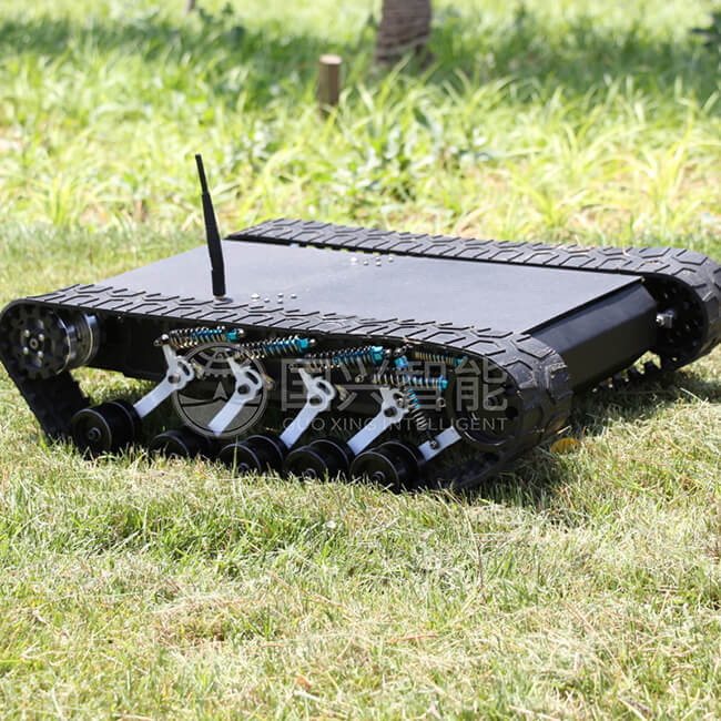
How do you choose the right base platform for your project? Selecting a tracks chassis requires strict mathematical evaluation. You cannot rely on visual aesthetics. Follow these proven criteria to validate your mechanical design.
Weight Distribution & Ground Pressure: You must evaluate the basic physics of your design first. The chassis must distribute your payload evenly across all road wheels. We calculate this as Nominal Ground Pressure (NGP). Uneven pressure causes the vehicle to sink in soft mud. It also forces the track pins to snap under localized stress. Ensure your center of gravity remains low and centered.
Maintenance Scalability: Think about emergency field repairs. How easily can a field operator break the track? You must evaluate track pin removal processes carefully. Dead tracks often use a simple retention ring. Live tracks might require a specialized C-clamp press. If your tension release mechanism is difficult to access, field maintenance becomes a nightmare.
Terrain Adaptation: Assess the vertical suspension travel of your system. Torsion bar systems offer excellent off-road compliance. They allow individual road wheels to move up and down freely. Basic bogie setups provide a simpler, stiffer alternative. Bogies group wheels in pairs, which works well for low-speed agricultural tasks but fails during high-speed off-road maneuvers.
Cost-to-Outcome Ratio: Always balance your upfront material costs against long-term reliability. Live-track rubber bushings and CNC-machined drive sprockets cost more initially. Compare this steep initial price against the severe operational cost of sudden field failures. A cheap chassis will inevitably throw a track in a critical situation, ruining your project timeline.
Even well-designed systems face severe mechanical threats in the real world. You must anticipate these implementation risks during your early prototyping phase. The transition from digital CAD to a physical testing environment often reveals hidden structural flaws.
The De-Tracking Threat
You must analyze the primary risk of track detachment constantly. De-tracking happens when lateral forces push the track teeth completely out of their drive sprocket alignment. Taking sharp, pivot turns in deep mud causes this failure frequently. The mud packs tightly into the sprocket teeth. This forces the tank treads to ride up and slip off the side. You can mitigate this by incorporating mud-clearing cutouts into your sprocket design and utilizing tall center guide horns on your track links.
Tensioning System Failures
Engineers must address the harsh realities of mechanical stretch. Metal track links wear down at the hinge pins over time. This friction grinds away millimeters of metal. Multiplied across eighty links, this wear lengthens the track loop significantly. If your idler wheel lacks a sufficient longitudinal adjustment range, the track will eventually sag and slip. You must design your idler arm to accommodate at least two full track links of stretch.
Friction and Power Loss
A tracked vehicle behaves entirely differently than a wheeled platform. A tracks chassis requires significantly more engine torque simply to move forward. Your power plant must overcome heavy internal mechanical resistance. Every hinge pin, rubber bushing, and sprocket tooth generates parasitic friction. We call this parasitic power loss. You must over-spec your electric motors or combustion engine by at least thirty percent compared to a wheeled vehicle of the exact same weight.
We never recommend building a physical track prototype blindly. Modern engineers use advanced digital tools to mitigate massive physical risks. You can save thousands of dollars by validating your geometry on a screen first.
Virtual Assembly Validation
Always use 3D CAD platforms to simulate your design. Software like SolidWorks, Fusion 360, or specialized kinematic simulators are invaluable. You must map out specific track paths precisely. Test complex mechanical constraints before you begin procurement. Emphasize testing physical interference between the track horns and the road wheels. Run kinematic animations to ensure the suspension travel does not cause the track loop to over-tighten and snap. Simulating these variables prevents extremely expensive manufacturing mistakes.
Vendor Shortlisting Logic
Use strict, evidence-based criteria for evaluating suppliers of continuous track systems. Do not settle for incomplete spec sheets.
Look for highly transparent load-rating data. The vendor must provide exact maximum tensile strength numbers for their track pins.
Demand clarity on replacement part availability. Track components are heavy wear items. You will definitely need spare pins, individual replacement links, and rubber road wheel pads eventually.
Review warranty constraints carefully. Many consumer-grade manufacturers void warranties instantly regarding high-torque, pivot-turning applications. Ensure your industrial use case matches their authorized operating parameters.
Attaching tank treads is an exercise in managing dynamic tension, not static fastening. You are balancing physics, friction, and engine power across a continuous floating loop. Successfully implementing a tracked system requires rigorous attention to mechanical detail.
Prioritize the engineering of your idler wheel tensioning system above all else. Proper tension prevents de-tracking.
Maximize your suspension travel limits to ensure continuous ground contact over uneven terrain.
A high-quality, expensive track remains entirely useless if the chassis cannot maintain proper sprocket alignment under heavy loads.
Always validate your track geometry in a CAD simulator before cutting any steel or purchasing rubber loops.
A: No, the treads are strictly isolated from the main hull. They are separated by the suspension arms, road wheels, drive sprockets, and idlers. Direct contact between the moving track and the armored hull would cause catastrophic friction, immense noise, and immediate structural damage to both components.
A: Mechanics connect them using thick metal track pins. These steel rods slide horizontally through interlocking hinges on each individual link. Some heavy systems secure these pins externally with end connectors. Others rely on central guide horns to keep the pins locked firmly inside the track assembly.
A: The repair process involves releasing all tension on the idler wheel first. Mechanics then physically break the track by driving out a connection pin. They realign the heavy track over the sprocket and road wheels using heavy winches or steel pry bars. Finally, they reconnect the link and reapply the correct tension.
A: Yes. Continuous rubber tracks are fully sealed loops. You cannot break them apart at a pin. The chassis must allow the front idler wheel to retract far enough inward. This creates enough slack to forcefully slip the entire enclosed rubber loop over the outer edge of the wheel assembly.